
Color Management for Navigator DFE: Inkjet Media, ICC Profiles, DeviceLinks, Spot Color, and Verification
Product: Xitron Navigator DFE (DuraFlex / DuraBolt / DuraCore)
Audience: Print operators, service technicians, dealers, and technically capable end users
Scope: Complete color management workflow from media qualification through production verification
Table of Contents
Introduction
Recommended Workflow Overview
What Color Management Does in the DFE
Key Concepts: Profiling, Calibration, Linearization, Tone Curves, and Render Configs
Media Selection and Qualification
Navigator NCE: Initial Profiling Configuration
Linearization and Ink Limiting / TAC
ICC Output Profile Creation
DeviceLink Profiles: Creation and Usage
Installing ICC and ICM Files in Navigator
Configuring the Color Profile in NCE
Rendering Intents
Black Point Compensation (BPC)
Black Preservation and RGB Black Handling
Spot Color and Pantone Handling
Measurement, Viewing Conditions, and Metamerism
G7 and GRACoL Considerations for Inkjet
Verification After Profiling
When to Re-Verify vs. When to Re-Profile
Troubleshooting Common Color Problems
Profile and Session Documentation Checklist
Source-Supported Claims Check
Summary
Further Reading
Introduction
Navigator DFE drives Xitron inkjet systems using a Harlequin RIP core. Color management in this environment involves a pipeline that starts with the incoming job's color data and ends with device-specific CMYK ink values sent to the printhead. Every step in that pipeline — media choice, linearization, ICC profiling, DeviceLink selection, rendering intent, and black handling — affects the final result.
This article documents the complete production color management workflow: from qualifying a new substrate through building ICC profiles and DeviceLinks, configuring the Navigator Configuration Editor (NCE), handling spot colors, verifying output, and diagnosing common problems.
Recommended Workflow Overview
The following sequence represents the recommended end-to-end workflow for adding a new inkjet media to Navigator. Each step is covered in detail in the sections that follow
- Qualify the media (confirm inkjet suitability, run test prints)
- Create NCE profiling configuration (Color Profile → Manual Calibration → Tone Curve → Render Config → Device Tab)
- Set up temporary Profiling workflow in client application
- Print and measure linearization / ink limit targets (set TAC, limit individual channels)
- Print and measure profiling target (IT8.7/4 or equivalent, after ink is fully dry)
- Generate ICC output profile (CoPrA, i1Profiler, or equivalent)
- Create DeviceLink from input standard to output profile (recommended)
- Install ICC and DeviceLink files on Navigator server
- Configure Color Profile in NCE (input/output profile or DeviceLink, rendering intent, BPC, RGB input)
- Verify output against reference
- Remove temporary Profiling workflow 12. Document: media name, TAC, profile filenames, rendering intent, date
What Color Management Does in the DFE
Navigator DFE processes incoming jobs through a color management pipeline built on the Harlequin RIP engine. Understanding what happens at each stage makes troubleshooting and configuration much more predictable.
The Color Pipeline
When a job arrives at the DFE, color data typically exists in one of several forms:
Device CMYK — values intended for a specific press standard (e.g., GRACoL, FOGRA51) or generated without a profile
Tagged CMYK — CMYK with an embedded ICC source profile
Device RGB — untagged RGB (sRGB or Adobe RGB assumed by default)
Tagged RGB — RGB with an embedded ICC profile
Spot/Named colors — Pantone or custom spot separations
The Harlequin RIP applies the configured color management transforms to convert all incoming colors to the device's native CMYK ink space, as characterized by the output ICC profile.
For Device CMYK input, if no intercept profile is configured, the CMYK values pass through without conversion. This is only appropriate when the incoming job has already been separated for your specific device. For all other cases, a source profile or DeviceLink should be configured.
The Render Config as the Connection Point
In Navigator, the Render Config is the object that ties ICC profiles, linearization data, tone curves, and device output settings together. A job submitted through a workflow that references a particular Render Config will use all of the color settings defined within it. This is why naming consistency across all related components matters.
Key Concepts
Linearization
Linearization brings the device's ink channels to a known, predictable response before the ICC profile is built. On most inkjet devices, printing a 50% dot value does not produce a 50% optical response due to dot gain, ink absorption, and hardware variation. Linearization applies correction curves to each ink channel individually to achieve a stable, repeatable tone response.
Linearization is a prerequisite for ICC profiling. The ICC profile characterizes the device in its current state — if that state is not linearized, the profile will characterize an inconsistent device and will not be transferable if anything changes.
In Navigator, linearization data can be applied through Tone Curves in the NCE and/or through the linearization step built into profiling software such as CoPrA or i1Profiler.
Ink Limiting and Total Area Coverage (TAC)
Total Area Coverage (TAC) is the sum of all ink channel percentages at any given point. For example, a neutral shadow area might use 80% C + 70% M + 70% Y + 90% K = 310% TAC.
Inkjet devices have physical TAC limits determined by the media's ability to absorb ink. Exceeding the TAC limit causes ink pooling, show-through, slow drying, mottling, or damage to the media or device.
TAC limits must be established and enforced before building the ICC profile. The profile should be built from a target printed within the actual TAC limits of the device/media combination.
The TAC limit is media- and device-specific. Coated inkjet media typically supports higher TAC than uncoated or low-porosity substrates. Some substrates may only support TAC values below 200%, while high-quality inkjet coated stocks may support 300%+.
Calibration vs. Profiling
These terms are often used interchangeably in conversation but have distinct meanings:
Term | What it means |
|---|---|
Calibration | Bringing the device to a defined state — typically linearized or matching a target response |
Profiling | Characterizing the device in its calibrated state by measuring a color target and encoding the result as an ICC profile |
Linearization | A specific type of calibration that corrects per-channel tone response |
Tone Curve | A curve applied in the RIP that modifies ink percentages before printing; can encode linearization data or G7 corrections |
Render Config | In Navigator, the container that links a Color Profile, Tone Curve, and Manual Calibration to a set of device output settings (resolution, screening) |
Calibration ensures reproducibility over time. Profiling captures the device's color behavior at a given point in time. Both are needed for consistent, accurate color output.
Media Selection and Qualification
Why Inkjet-Treated Media Is Strongly Recommended
Not all papers are physically compatible with aqueous inkjet inks. Standard offset stocks, even high-quality coated sheets, are not designed to receive inkjet inks. Inkjet-treated media has a specialized coating or surface treatment that:
Absorbs ink quickly and evenly to prevent pooling
Prevents lateral ink spread (wicking), which reduces sharpness
Supports adequate gamut by holding colorant near the surface
Allows sufficient TAC without show-through or drying problems
Using non-inkjet-treated media is a common source of profiling failures. An ICC profile cannot compensate for ink that is pooling, wicking, or not drying correctly. If the media cannot physically accept the required ink load, no profiling or color management configuration will produce acceptable results.
Untreated Absorbent Media (e.g., Uncoated Offset, White Wove Envelopes)
Highly absorbent media such as uncoated bond, copy paper, and White Wove envelopes present specific problems:
Ink absorbs rapidly into the substrate, reducing optical density and saturation
Colors appear muted compared to inkjet-treated stocks
Fine detail may bleed due to lateral ink spread
Profiles built on these stocks will have narrower gamuts and may not achieve acceptable Pantone or brand color matches
These stocks can be profiled if the application requires them, but TAC will typically need to be set conservatively and color accuracy expectations must be adjusted accordingly.
Smooth or Coated Non-Inkjet Stocks
Offset-coated stocks and other smooth papers without inkjet treatment may:
Cause ink to pool on the surface rather than absorbing
Result in mottle, streaking, or uneven ink distribution
Dry very slowly or incompletely, leading to smearing or blocking
Require extremely low TAC values to avoid physical damage
Some materials in this category may be usable at low ink loads for specific applications, but they should be tested extensively before any profiling work is done.
Media Qualification Procedure
Before spending time on profiling, confirm the following:
Ink adhesion test: Print a solid block of each process color at 100% and allow to dry fully. Ink should adhere firmly with no smearing, beading, or flaking.
TAC test: Print a graduated TAC ramp (e.g., 100% to 400% in 25% steps) and identify the point at which ink pooling, bleeding, or drying failure begins. Set your TAC limit below this point.
Uniformity test: Print solid areas of each process color and inspect for mottling, streaking, or uneven ink distribution. These are signs that the media is not compatible or that device maintenance is needed.
Drying time test: Measure a patch immediately after printing and again after the recommended drying time. If values shift significantly, allow more drying time before measuring profiling targets.
Sharpness test: Print fine linework and type at various orientations. Wicking or absorption issues will show as ragged edges.
Warning: If the media fails the ink adhesion or TAC tests, do not proceed with profiling. Media qualification is a prerequisite, not an optional step.
Navigator NCE: Initial Profiling Configuration
The Navigator Configuration Editor (NCE) is the web-based interface for configuring all color management settings. Open it in a browser at:
http://localhost:81/NCE/index.html
Note: This URL and the NCE configuration interface described in this article apply across many years of Navigator releases. If accessing the NCE remotely, substitute the server's IP address or hostname for
localhost.
The following steps create a complete, named configuration set for a new media. Use the same name throughout — this is referred to as [Media Name] in the steps below. Replace this with your actual stock name (e.g., CoatedMatte90g or BannerVinyl). Do not use spaces in names if your Navigator version does not support them; use underscores or CamelCase consistently.
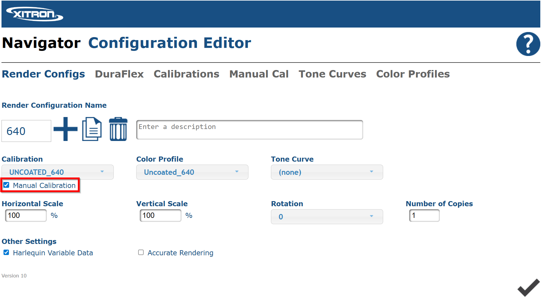
Step 1: Enable Manual Calibration
On the main NCE page, confirm that Manual Calibration is checked. This enables the Manual Calibrations tab and allows tone curve and calibration data to be applied through the Render Config.
Step 2: Create a Color Profile
Go to the Color Profiles tab.
Click the button to create a new Color Profile.
Name it [Media Name].
Uncheck all options that are enabled by default. You will configure these after the ICC profile has been built and installed (see Configuring the Color Profile in NCE).
Click the checkmark to save.
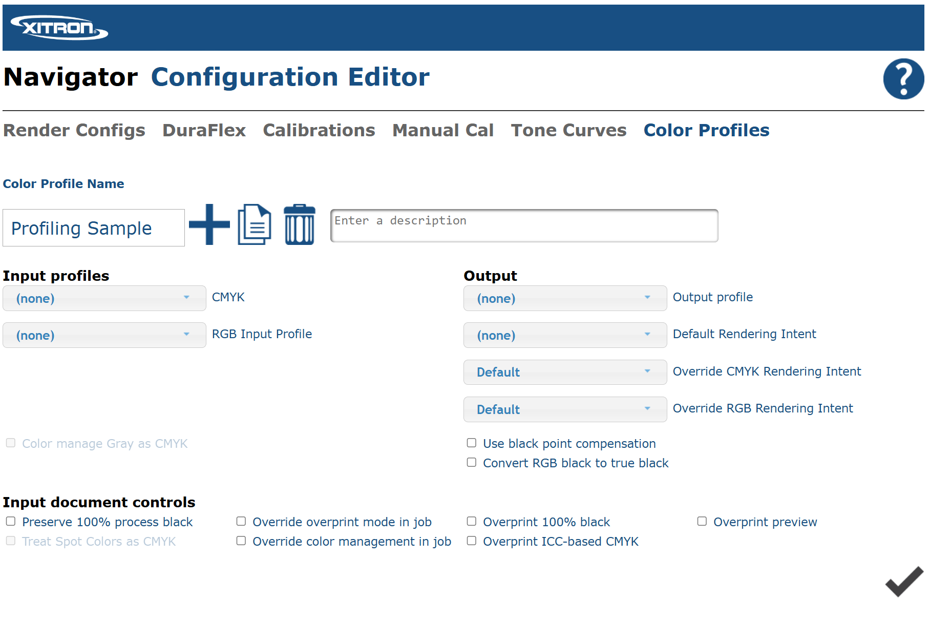
Best practice: The Color Profile name is what operators and end users will see when selecting media in production. Use a name that is descriptive and consistent with how the stock is identified in your workflow.
Step 3: Create a Manual Calibration
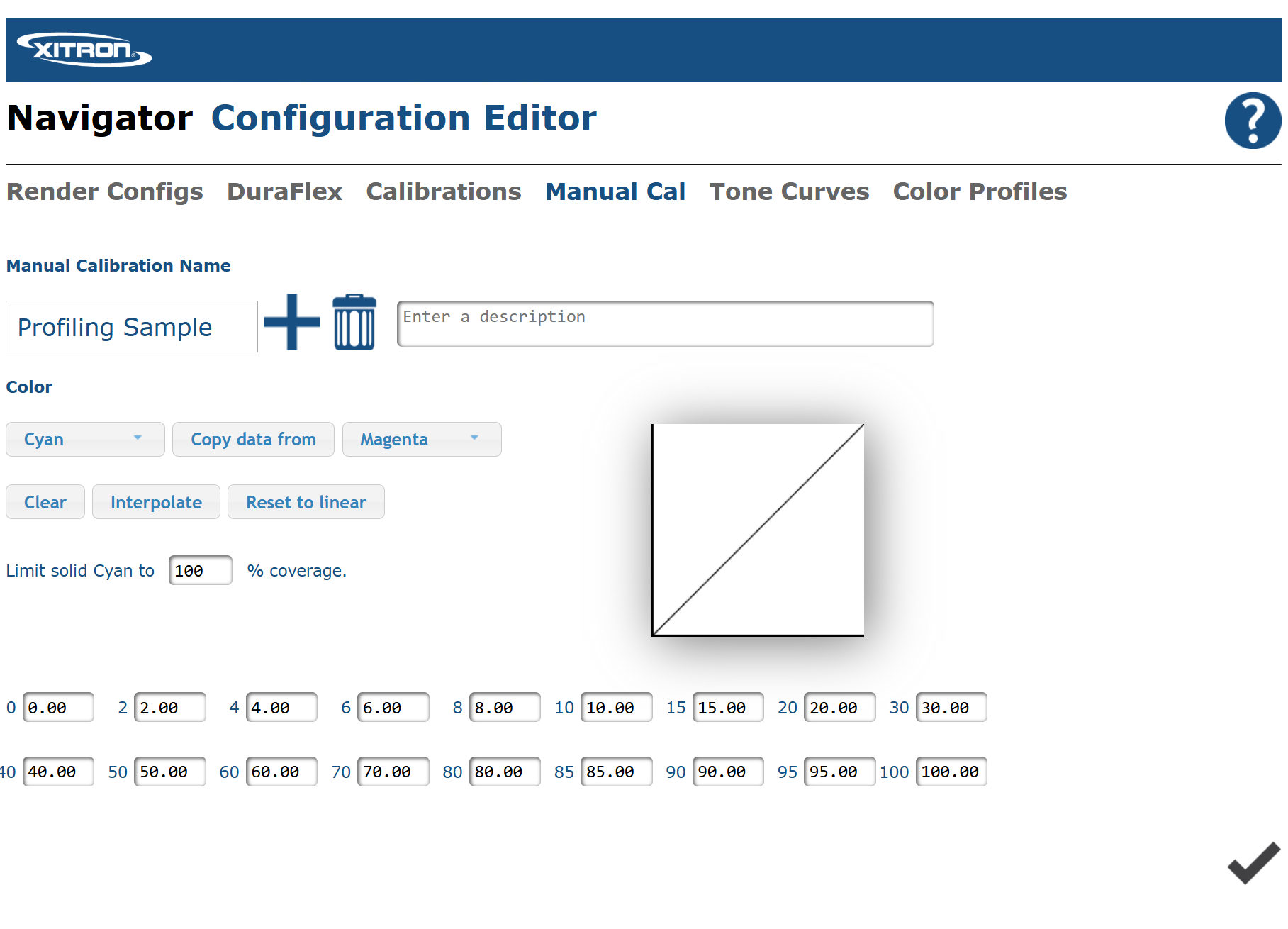
- Go to the Manual Calibrations tab.
- Create a new Manual Calibration.
- Name it [Media Name] — exactly as you named the Color Profile.
- Leave all settings at their default values for now. These can be updated later if measurement-based calibration data is available.
- Click the checkmark to save.
Step 4: Create a Tone Curve
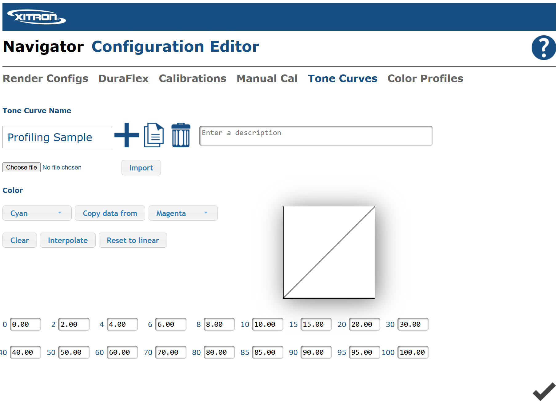
Go to the Tone Curves tab.
Create a new Tone Curve.
Name it [Media Name].
Leave it as the default (linear) tone curve for initial profiling. This curve can be updated later with per-channel linearization data or G7 correction curves if required (see Linearization and Ink Limiting).
Click the checkmark to save.
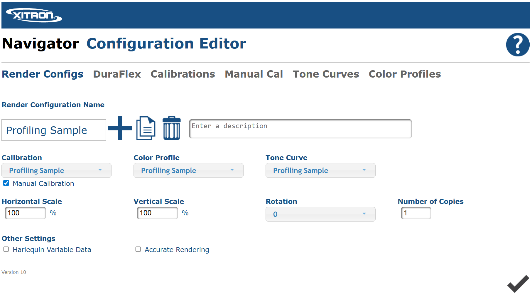
Step 5: Create a Render Config
Go to the Render Configs tab.
Create a new Render Config.
Name it [Media Name].
Set the following fields to the entries you just created:
Color Profile: [Media Name]
Tone Curve: [Media Name]
Calibration: [Media Name]
Click the checkmark to save.
Step 6: Configure the Device Tab
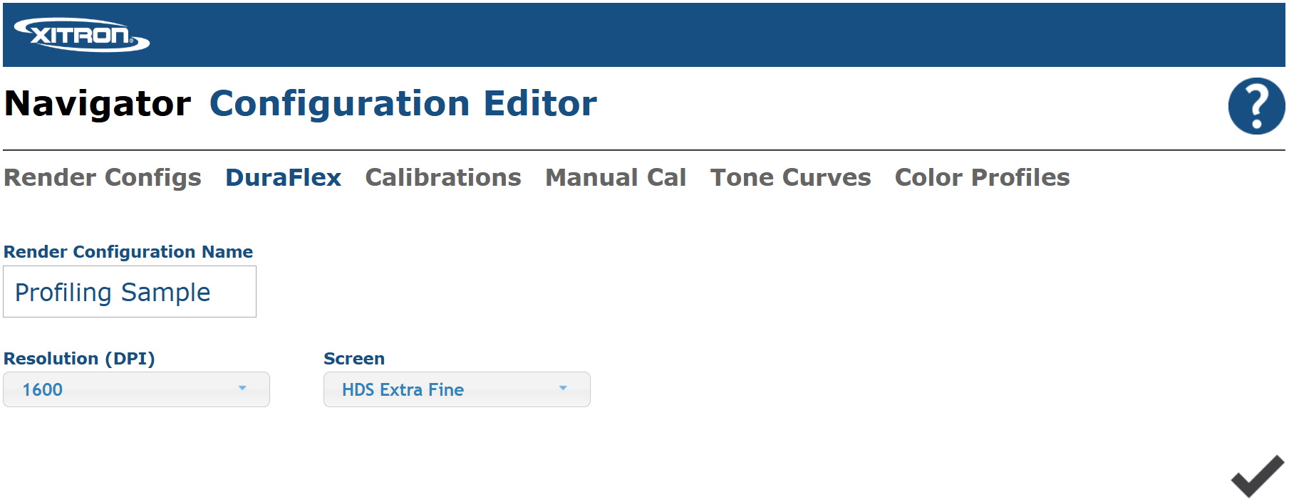
The Device tab is located immediately to the right of the Render Configs tab. Its label shows the device type (DuraFlex, Bolt, Core, etc.), but the function is the same across all models.
Select the Render Config you just created ([Media Name]).
Select the desired resolution. Note that a separate Render Config and ICC profile is technically required for each resolution, as ink laydown and dot gain characteristics differ.
Select the desired screening method.
Click the checkmark to apply the change.
Warning: Changing the resolution or screening method after profiling has been completed will invalidate the profile. The profile characterizes the device's behavior at a specific resolution and with a specific screening method. Always profile at the resolution and screening combination you intend to use in production.
Step 7: Set Up the Profiling Workflow in the Client Application
Open the client application.
Duplicate an existing DFE workflow and name the duplicate something like
Profiling_[Media Name]. This name is for operator clarity only — this workflow is temporary.In the workflow editor, go to the Render section and find the Configuration pull-down.
Select the Render Config you created: [Media Name].
Click the pencil icon to exit the editor and save changes.
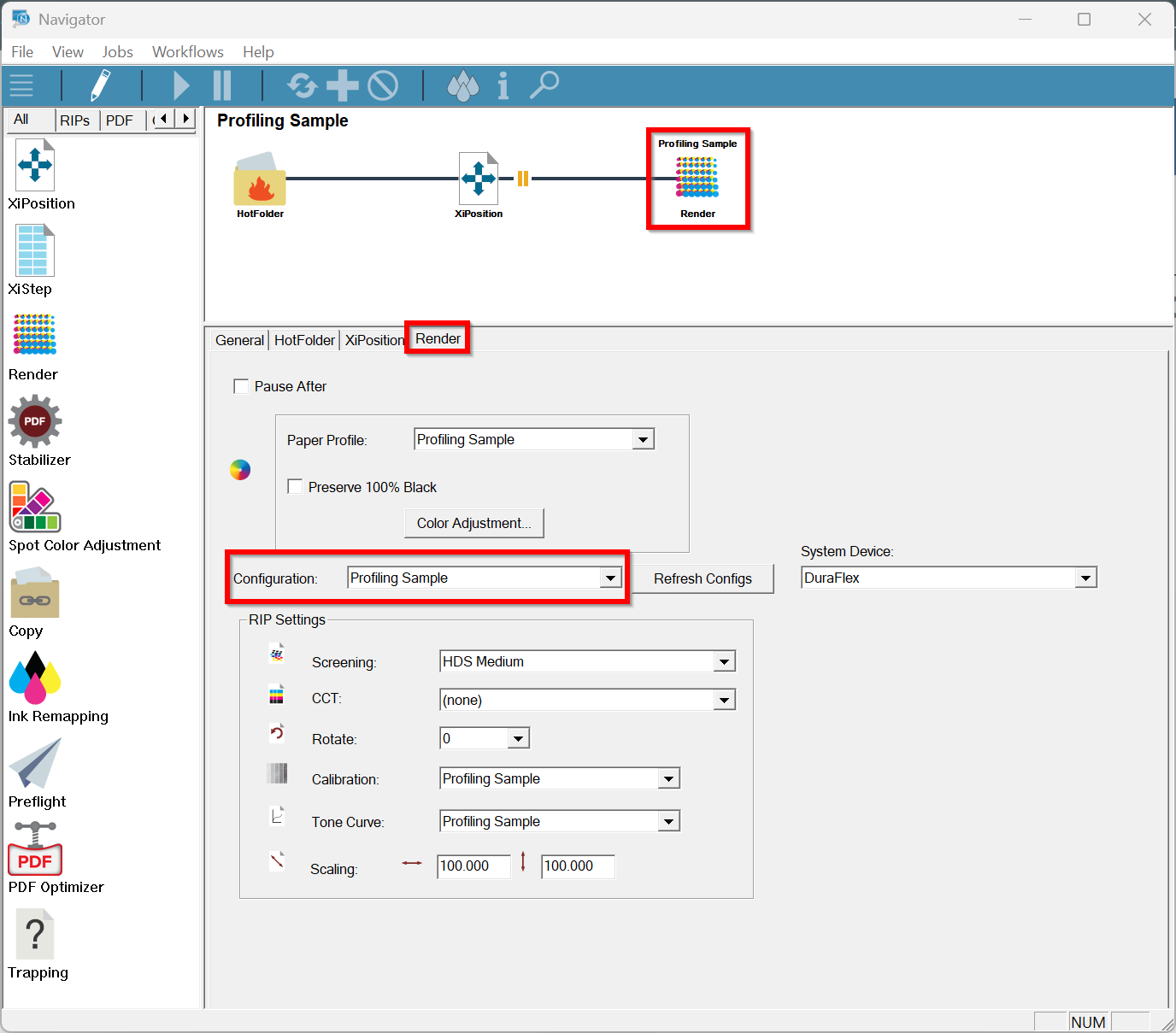
The system is now prepared to output linearization and profiling targets through the temporary Profiling workflow, either by submitting jobs through the client application or by dropping them into a hot folder associated with this workflow.
Best practice: After profiling is complete and the ICC profile is confirmed working in production, delete the temporary Profiling workflow. Leaving unused workflows in the client application creates confusion for operators and increases the risk of jobs being sent through an incorrect workflow.
NOTE: Depending on the software package you are using for profiling, or if you specifically want to iterate for accuracy when creating the ICC profile, or when generating a device link, you will need to drop the intermediaty ICC/ICM files into C:\Navigator\Navigator\Config\RenderConfig\ICC Profiles. You would go back to Step 2 and then select either the temporary output file and save, or the temporary device link profile prior to printing the next sheet. Be sure to save the change by clicking the checkmark.
Linearization and Ink Limiting / TAC
Why This Step Cannot Be Skipped
Linearization and TAC limiting must occur before profiling. Building a profile on an unlinearized or TAC-over-limit device characterizes an unstable, inconsistent state. If the device drifts or if TAC is later constrained, the profile will no longer match the device's actual behavior.
Establishing the TAC Limit
Print a TAC ramp target through the Profiling workflow and identify the maximum TAC at which the media accepts ink without pooling, mottling, or slow drying. Set your TAC limit conservatively below this value — typically 5–10% below the observed failure point.
TAC limiting is applied in the profiling software before the profiling target is generated. Both CoPrA and i1Profiler support TAC limiting as part of the linearization process.
Important: G7 calibration methodology requires printing patches at up to 300% TAC. Many inkjet/media combinations cannot support this. See G7 and GRACoL Considerations for Inkjet for why this matters.
Per-Channel Ink Limiting
In addition to the total TAC limit, individual ink channels may also need to be limited. If a single channel reaches 100% before the gamut is optimized, or if one channel causes specific media problems at high density, per-channel limits can be applied in the profiling software.
Linearization
With the TAC limit established, print a linearization target (typically ramps for C, M, Y, K, and optionally channel combinations) through the Profiling workflow. Measure the target with a spectrophotometer and apply the linearization corrections through your profiling software.
In Navigator, you can also import linearization correction curves (in CGATS format) directly into the Tone Curves tab. If this approach is used, the corrected Tone Curve must remain assigned to the Render Config used for profiling and production.
Drying time: Allow profiling targets to dry fully before measuring. The required drying time is media- and ink-dependent. Measuring before the ink has stabilized produces measurements that do not represent the final printed result and will lead to an inaccurate profile. When in doubt, wait longer. Some media requires 30 minutes or more; some require overnight.
ICC Output Profile Creation
Choosing a Profiling Software Package
Several profiling software packages can produce high-quality production ICC profiles. They differ in their level of automation, DeviceLink capabilities, spot color iteration tools, measurement cleanup features, TAC control, and reporting depth.
ColorLogic CoPrA
CoPrA is the ICC profiling component of the ColorLogic suite (current release: CoPrA 11 as of September 2024). It creates printer profiles, DeviceLink profiles, and SaveInk profiles for any color space, including multicolor. Key features relevant to Navigator workflows:
Per-channel and total ink limiting controls
DeviceLink profile creation (CMYK–CMYK, RGB–CMYK, and other combinations)
SaveInk profiles for ink reduction
Integration with ColorAnt for measurement cleanup and chart creation
Integration with ZePrA for automated workflow deployment
ColorLogic CoPrA is an Xitron-resold product. Contact your Xitron representative for current pricing and licensing options.
ColorAnt is not a profiling tool. ColorAnt (current release: ColorAnt 11 as of December 2024) is used for chart creation, measurement import, data correction, spectral editing, and optimization of measurement data. It is a companion to CoPrA, not a replacement. If your goal is to generate ICC or DeviceLink profiles, CoPrA is required.
Further reading:
CoPrA product page — colorlogic.de
ColorAnt product page — colorlogic.de
X-Rite / Calibrite i1Profiler
i1Profiler is a well-established profiling package used in many commercial print environments. It supports custom profiling chart layouts and is widely compatible with X-Rite and Calibrite spectrophotometers. Before selecting i1Profiler, verify current instrument and OS compatibility with X-Rite / Calibrite, as software and hardware support changes between versions.
Note: Do not assume that an older i1Profiler license or an older spectrophotometer model is compatible with a current OS or current workflow. Verify compatibility with X-Rite / Calibrite before purchasing or committing to this toolchain for a new deployment.
Further reading:
X-Rite i1Profiler product page — xrite.com
ZePrA (ColorLogic Color Server)
ZePrA is a full-featured color server (current release: ZePrA 13 as of July 2025) that automates color conversions via DeviceLink profiles. ZePrA can build DeviceLinks on-the-fly using its SmartLink engine, iterate spot color matching, and manage TAC reduction across production workflows. It is appropriate for high-volume operations or shops requiring automated, queue-based color management. ZePrA is a separate product from CoPrA and is not required for basic ICC profiling.
Further reading:
ZePrA product page — colorlogic.de
The Profiling Target
The most common profiling chart for CMYK inkjet characterization is the IT8.7/4 (also called ECI 2002), which contains 1,617 color patches covering the device gamut systematically. Print this target through the Profiling workflow with all ICC-based color management set to passthrough (no input profile, no conversion). Measure after full drying.
Larger targets (e.g., IT8.7/5 with 4,028 patches) can improve profile accuracy, especially for wide-gamut inkjet systems, by providing more data points for the profiling software to characterize the gamut.
Profile Naming
Name the output ICC profile clearly and consistently:
[MediaName]_Output.icc— the printer output profile[MediaName]_FOGRA51_DL.icc— a DeviceLink from FOGRA51 to the output profile
Use names that unambiguously identify the media, the source standard (if applicable), and the profile type. Avoid spaces in filenames.
DeviceLink Profiles: Creation and Usage
What a DeviceLink Profile Does
A DeviceLink ICC profile encapsulates a color transform between a specific source color space and a specific destination color space in a single optimized conversion step. Harlequin RIP documentation quote:
"A devicelink profile encapsulates one rendering intent from one ICC source/destination profile pair. They are popular because they can provide superior fidelity due to the gamuts of both the source and destination profiles being available at the time the devicelink profile was created. One popular feature built-in to many devicelink profiles is the preservation of the black channel when CMYK is transformed to CMYK. This is not possible in a standard transform using source and destination profiles due to the 4-3-4 channel conversions."
For Navigator inkjet workflows, the most common DeviceLink configuration is:
Input standard (e.g., GRACoL 2013, FOGRA51) → Output printer ICC profile.
This allows production jobs prepared for a commercial offset standard to be printed on the inkjet device with a single, optimized conversion that preserves black separation structure.
Advantages of DeviceLinks over Source+Destination Profile Pairs
Black channel preservation: CMYK–to–CMYK conversion through a DeviceLink can preserve or remap the K channel explicitly. A standard two-profile conversion routes through Lab (4→3→4), losing the K channel information.
Single-step accuracy: Both source and destination gamuts are available during DeviceLink creation, allowing more informed gamut mapping decisions.
Consistent results: Once a DeviceLink is created and deployed, every job processed through it receives the same conversion — no variation from rendering intent changes or profile pairing decisions at the operator level.
Disadvantages of DeviceLinks
Per Harlequin documentation:
"There are also significant disadvantages to using devicelink profiles versus standard source/destination profile pairs: they only apply to a particular pair of source and destination profiles which restricts their applicability; they contain only one of the three unique rendering intents normally available in an ICC output profile."
A DeviceLink is only valid for its specific source–destination combination. If the output profile is updated (e.g., after a device service or media change), the DeviceLink must be recreated.
A DeviceLink contains only one rendering intent. Creating multiple DeviceLinks (e.g., one for Relative Colorimetric and one for Perceptual) is required if multiple intents are needed.
BPC and DeviceLinks
BPC cannot be applied to a DeviceLink transform. This is confirmed in Harlequin documentaion:
"This specification only applies to source/destination ICC profile pairs. BPC cannot be applied if an ICC devicelink is used."
Shadow handling must be addressed within the DeviceLink itself at creation time, not by applying BPC afterward. CoPrA's DeviceLink creation tools allow this to be configured during profile building.
When to Use a DeviceLink vs. Source+Output Profiles
Scenario | Recommendation |
|---|---|
Production jobs prepared for a known offset standard (GRACoL, FOGRA51, SWOP) | DeviceLink (standard → output) |
Wide variety of incoming source profiles, no single dominant standard | Source+Output profile pair |
CMYK–to–CMYK with black preservation required | DeviceLink |
Proofing simulation (paper white simulation) | Source+Output with Absolute Colorimetric |
RGB photography or mixed-content jobs | Source+Output (sRGB or AdobeRGB → output) |
Installing ICC and ICM Files in Navigator
After generating the ICC output profile and any DeviceLink profiles, copy them to the ICC Profiles directory on the Navigator server.
The ICC Profiles directory path is:
C:\Navigator\Navigator\Config\RenderConfig\ICC Profiles
Both the output ICC file and any DeviceLink .icc / .icm files must be placed in this directory. After copying the files, return to the NCE to configure the Color Profile.
Note: ICC files use the
.iccextension; ICM files use the.icmextension. These formats are functionally equivalent for Navigator purposes. Both extensions are valid ICC profile containers defined by the ICC specification.
Configuring the Color Profile in NCE
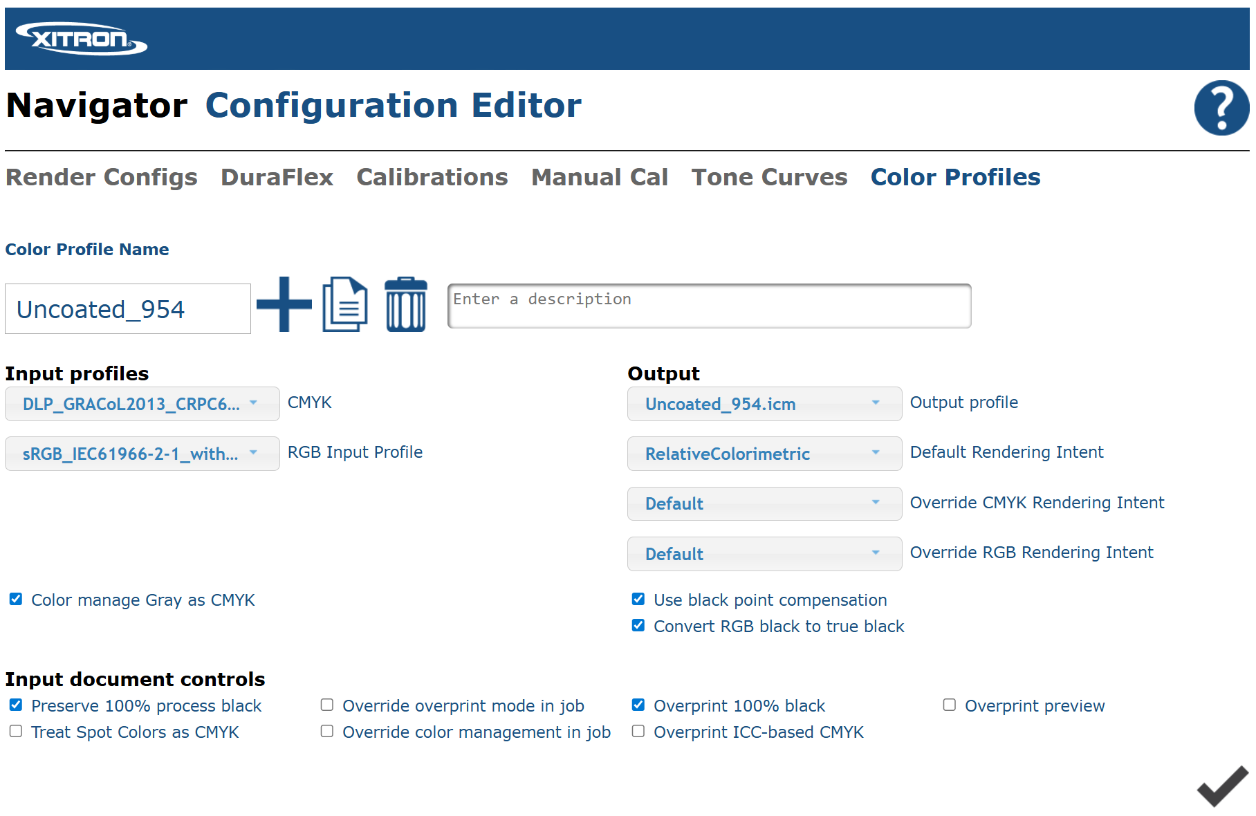
With ICC profiles installed, return to the Color Profiles tab in NCE and select your [Media Name] profile. Configure it as follows.
Input CMYK Profile
Select the DeviceLink profile in the Input CMYK Profile field if you are using a DeviceLink workflow. The DeviceLink encapsulates both the source and destination profiles in a single transform.
If you are using separate source and output profiles (without a DeviceLink), select the appropriate CMYK source profile here (e.g., GRACoL 2013, FOGRA51).
Output Profile
Select the [Media Name] output ICC profile you created. This is the profile that characterizes your specific device and media combination.
If a DeviceLink is selected in the Input CMYK field, the output profile is typically embedded within the DeviceLink. Consult your profiling software's documentation for how it handles the output profile reference in DeviceLink workflows.
RGB Input Profile
This setting determines how untagged RGB content — images and graphics without an embedded ICC profile — is interpreted. It does not affect RGB content with embedded profiles; those are handled by the profile's source definition.
Profile | When to Use |
|---|---|
Adobe RGB (1998) | Customers primarily using professional design tools (Adobe InDesign, Illustrator, Photoshop) and producing files for commercial print. Wider gamut; appropriate for print reproduction workflows. |
sRGB | Customers producing files from general business software (Microsoft Office), consumer cameras, or web-originated content. Narrower gamut but the de facto standard for screen-based workflows and most consumer devices. |
When you receive a mixture of file types from varied sources, sRGB is the safer default choice. Its narrower gamut reduces the risk of unexpected out-of-gamut surprises; files that would exceed sRGB gamut are typically professionally produced and will carry embedded profiles.
Rendering Intents
Rendering intent controls how out-of-gamut colors are handled when converting between color spaces. The choice of rendering intent affects the appearance of colors throughout the gamut — not just those that are technically out of gamut.
Intent | Behavior | Best for | Caution |
|---|---|---|---|
Relative Colorimetric | Maps source white point to media white point. Out-of-gamut colors are clipped to the nearest reproducible value. In-gamut colors are preserved colorimetrically. | Production CMYK workflows; most commercial print applications; any workflow where in-gamut accuracy matters | Out-of-gamut colors are clipped, not compressed — saturated colors may be abruptly cut off |
Absolute Colorimetric | Same as Relative Colorimetric but preserves the source white point, simulating the paper color of the source profile's reference condition. | Proofing (inkjet proofer simulating offset paper); paper simulation workflows | Not typically the default for production printing on the actual output substrate; may produce unexpected results if the source and destination paper whites differ significantly |
Perceptual | Compresses the entire source gamut to fit within the destination gamut, preserving relationships between colors at the cost of some gamut compression. The exact behavior is ICC-profile-vendor-dependent. | Photographic and natural-image workflows where smooth gradients and tonal relationships matter more than colorimetric accuracy | Perceptual intent behavior is not standardized across profiles and profiling software; results may differ between vendors. Not recommended for critical brand color or Pantone reproduction. |
Saturation | Preserves color saturation at the expense of accuracy in hue and lightness. | Business graphics; presentations; vivid graphics where vividness takes priority over accuracy | Not appropriate for critical color reproduction. This intent was labeled "Business Graphics" in early Harlequin MultiRIP color management systems. |
Recommended default: Relative Colorimetric with Black Point Compensation enabled (see next section). This is the standard for commercial offset print equivalence and is appropriate for the majority of production CMYK inkjet workflows.
The Harlequin RIP supports rendering intent overrides at both the job level and the object level. Object-based intent overrides allow different intents to be applied to images versus text versus linework within a single job. This is an advanced feature; consult the Harlequin documentation if this level of control is required.
Black Point Compensation (BPC)
What BPC Does
Black Point Compensation (BPC) is defined in ISO 18619, Image technology colour management — Black Point Compensation, which is incorporated in the source materials for this article.
BPC adjusts the color transform between source and destination ICC profiles to account for differences between the darkest level of black achievable by the source and destination color spaces. Without BPC:
Shadows in the source color space may be mapped to a value that is too light on the destination device (if the destination has a deeper black)
Or shadows may be crushed to pure black, losing shadow detail (if the source has a deeper black than the destination)
BPC applies a linear scaling function that maps the source black point to the destination black point, ensuring that the full tonal range of the source is distributed across the full available tonal range of the destination. The ISO 18619 standard specifies that BPC is computed from the source and destination ICC profiles and the rendering intent — it does not depend on the specific image content being processed, which means it can be computed once per profile pair and applied efficiently across many jobs.
When BPC Applies and When It Does Not
Condition | BPC Applies? |
|---|---|
Relative Colorimetric intent, source+output ICC profiles | Yes — recommended |
Perceptual intent, source+output ICC profiles | Yes — BPC can be applied |
Saturation intent, source+output ICC profiles | Yes — BPC can be applied |
Absolute Colorimetric intent, any profiles | No — BPC has no effect on absolute intent transforms |
ICC DeviceLink profile in use | No — BPC cannot be applied to DeviceLink transforms |
BPC and DeviceLinks: When using a DeviceLink in the Input CMYK profile slot, BPC will have no effect. Shadow rendering must be addressed within the DeviceLink at the time of creation. This is not a limitation of Navigator — it is a fundamental property of DeviceLink profiles as defined by the ICC specification.
Recommendation
Enable BPC for all production workflows using source+output ICC profile pairs with Relative Colorimetric or Perceptual intent. This is standard practice for commercial print workflows and is recommended by the ISO 18619 specification authors.
What BPC Cannot Fix
BPC is not a general-purpose color correction tool. It cannot:
Fix a profile built from bad measurement data
Compensate for media that is not holding ink correctly
Correct for wrong TAC settings
Compensate for a profile that does not match the device it was built from
Correct for wrong profile selection (using the wrong profile for a given stock)
Black Preservation and RGB Black Handling
Black Preservation
The Harlequin RIP provides a black preservation feature that prevents color management from converting pure black objects (linework, text) through the full color transform, which would typically produce a rich CMYK black that can cause ink spread on fine detail and mis-registration issues.
From Harlequin documentation:
"Color managing black usually results in a non-pure color which could be undesirable for text or linework. Black preservation is used for preserving black channel values across color transforms... Black preservation only applies to black linework and text objects, that is, it does not apply to images or shadings."
Two types of black preservation are available:
100% black preservation: Preserves the 100% K value through the color transform, outputting a solid K-only black regardless of what the ICC transform would have produced.
Rich black preservation: Preserves the black channel values as-is when converting CMYK–to–CMYK, preventing the K channel from being redistributed into CMY during a color conversion.
Recommendation: Enable 100% black preservation for text and linework in production CMYK workflows. This prevents small text from becoming a rich CMYK build, which improves sharpness and reduces the risk of color fringing from mis-registration.
RGB Black Handling
When a job contains RGB content that uses RGB black (R=0, G=0, B=0), the color management pipeline will typically convert this to a CMYK value through the output profile. Depending on the ICC profile and rendering intent used, this can produce a rich four-color black rather than a K-only black.
If K-only black is required for text or fine linework in RGB source content, configure the Harlequin color management to intercept and convert RGB black to K-only before the output transform.
Note: Black preservation settings in Navigator are configured through the NCE Color Profile settings. Consult current Navigator DFE documentation for the specific UI controls available in your version.
Spot Color and Pantone Handling
How the Harlequin RIP Handles Spot Colors
The Harlequin RIP uses Named Color Databases (NCDs) to resolve spot color names to device values. When a job contains a spot separation named, for example, PANTONE 485 C, the RIP searches the configured NCD list for a matching entry. If found, it substitutes the device values from the NCD. If not found, it falls back to the alternate color space defined in the job file (typically a CMYK approximation embedded by the originating application).
Pantone has supplied color data using both M1 and M2 measurement modes, both databases are provided. The M1 database has the _M1 suffix on the resource file name; the database with no suffix is M2 data. See Measurement, Viewing Conditions, and Metamerism for the significance of M1 vs. M2.
The RIP uses the first NCD in the configured list that contains a match for a given spot color name. If you need to override the values in a standard NCD (for example, to use customer-supplied measured values for a brand color), add your custom NCD to the beginning of the NCD list.
The Gamut Problem
Media gamut is the fundamental limiting factor for Pantone reproduction. Every device has a gamut — the set of colors it can physically reproduce on a given substrate with a given ink set. Many Pantone spot colors were defined for specific offset ink formulations and fall outside the CMYK gamut of inkjet devices, especially on lower-gamut or uncoated substrates.
When a Pantone color is out of gamut, the best achievable result is the nearest reproducible color. No profiling, color management configuration, or device setting can produce a color that the physical device cannot reproduce on the given substrate.
This means the first step in Pantone color evaluation is to determine whether a given color is achievable. Measure the target LAB value and compare it to the device's gamut boundary (available in most profiling software). Be transparent with customers about which colors are within gamut and which are not.
Licensed Pantone Color Data
Accurate Pantone reproduction requires access to licensed Pantone color data. Do not rely on Pantone LAB values found through informal online sources; the licensing status and accuracy of such data is uncertain, and Pantone's licensing terms have changed significantly in recent years with the transition to subscription-based access.
Recommended approaches for obtaining Pantone target values:
Licensed Pantone libraries in your profiling or color management software (CoPrA, ZePrA, i1Profiler, and others include licensed Pantone data in their named color databases)
Pantone Color Bridge Guides (physical coated and uncoated editions) — Pantone's own CMYK process equivalent values for each spot color on coated and uncoated stock
Pantone Connect / PantoneLIVE — Pantone's current subscription-based digital color standard platform
Customer-supplied spectral or LAB targets — measured brand standards from the customer's own specification documents or physical samples
Spot Color Iteration
For Pantone or brand colors that must be closely matched on a specific substrate, an iterative approach is required:
Start with the NCD value for the Pantone color (from a licensed database). Submit a print through the production Render Config (not the Profiling workflow) and measure the result.
Calculate the delta-E between the measured value and the target LAB.
Adjust the CMYK values in the Spot Color Editor and reprint. Iterate until delta-E is minimized.
Evaluate visually under controlled lighting (see Viewing Conditions). Colorimetric accuracy (low delta-E) and visual acceptance are related but not identical — metamerism can cause a colorimetrically close match to appear different under certain lighting conditions.
ZePrA's Spot Color Iteration wizard automates this process for high-volume workflows by printing, measuring, and recalculating iteratively until a target delta-E threshold is reached.
Delta-E Expectations
Context | Typical Acceptable dE (CIEDE2000) |
|---|---|
Commercial offset brand match | ≤ 2.0 |
Packaging / brand-critical | ≤ 1.5 |
Wide-format display, viewed at distance | ≤ 3.0 |
Proof-to-press match (ISO 12647-7) | ≤ 3.0 average, ≤ 6.0 maximum |
Reminder: delta-E tolerance must be evaluated under the same viewing conditions used for production sign-off. A visually acceptable match under D50 may not appear acceptable under fluorescent office lighting due to metamerism (see next section).
Measurement, Viewing Conditions, and Metamerism
Measurement Mode: M0, M1, M2, M3
The ISO 13655 standard defines four measurement modes for spectrophotometers, which affect how the spectrophotometer's illumination interacts with the sample. The ICC profile specification (incorporated in the source materials for this article) defines the encoding for these modes:
Mode | Illumination | Primary use case |
|---|---|---|
M0 | Tungsten (unfiltered) — traditional reference illuminant | Legacy/interoperability with older instruments and standards |
M1 | D50-equivalent (UV-regulated) | Current standard for graphic arts ICC profiles; accounts for optical brighteners in a controlled way |
M2 | UV-cut filter applied | Eliminates the contribution of optical brighteners entirely; useful for diagnosing OBA effects |
M3 | Polarizing filter applied | Eliminates specular reflection; used for wet ink measurement |
For new ICC profiles in Navigator workflows, measure and build profiles using M1 unless a specific customer or certification requirement specifies a different mode. M1 is the current ISO 13655 standard for graphic arts measurement and is the mode used by Pantone for its M1 color data.
Ensure the spectrophotometer being used supports the required measurement mode. Not all instruments support all modes.
Optical Brightening Agents (OBAs)
Many papers — particularly those marketed as "bright white" — contain optical brightening agents (OBAs). OBAs are fluorescent compounds that absorb UV light and re-emit it as visible blue-white light, making the paper appear brighter and whiter than it physically is under UV-containing illumination.
OBAs complicate color measurement and visual color evaluation:
Measurement mode matters: M0 and M1 measurements will reflect OBA fluorescence differently because they use different UV levels. A profile built under M0 may not match visual expectations under D50 illumination, and vice versa.
Viewing light matters: The apparent paper white — and therefore all colors on that paper — will change depending on the UV content of the viewing light source. A paper with heavy OBAs will look noticeably different under a low-UV incandescent source versus a UV-rich fluorescent tube.
Proofing papers often have high OBA content. Comparing an inkjet proof to a press sheet under the same light may show a mismatch due to OBA differences between substrates, even if the ICC profiles are accurate.
Best practice: Note the OBA content of substrates being profiled. When comparing prints for color approval, ensure all samples are evaluated under the same light source simultaneously.
Metamerism
Metamerism is the phenomenon where two color samples appear identical under one light source but different under another. In practical print terms:
Illuminant metamerism (most common): A Pantone match that looks correct under D50 may look visibly different under cool-white fluorescent office lighting or warm tungsten. This is not a defect in the print — it is a physical consequence of different ink pigment combinations producing the same colorimetric response under one illuminant but not another.
Observer metamerism: Different observers perceive the same color sample differently due to individual biological variation in cone cell sensitivity. Color approval should ideally involve multiple evaluators.
Geometric metamerism: Color appearance changes with viewing angle, particularly on metallic, pearlescent, or textured substrates.
For more information on metamerism:
What is Metamerism? — X-Rite — xrite.com
Metamerism (color) — Wikipedia) — wikipedia.org
D50 Viewing Conditions
The ISO 3664 standard defines D50 (5000 K daylight simulation) as the reference illuminant for color evaluation in graphic arts. All ICC profile color data is referenced to D50.
All color-critical print evaluation — Pantone matching, proof-to-press comparison, brand color sign-off — must be performed under a D50-calibrated light source. Evaluating color under uncalibrated office fluorescent lighting or tungsten lamps is a primary source of color disputes that have no relationship to the accuracy of the print.
Investment recommendation: A D50-calibrated light booth at the press station is not optional for operations performing contract color or Pantone matching work. Affordable tabletop light booths from GTI, Just Normlicht, or similar vendors provide the controlled viewing environment necessary for reliable color decisions.
Drying Time
Ink on paper continues to change colorimetrically for some period after printing as it dries and oxidizes. Profiling targets and spot color iteration patches must be measured only after the ink has fully stabilized. Measuring too early will produce measurements that do not represent the final printed result.
Minimum recommended drying time varies by media and ink:
Inkjet-treated coated stocks: typically 15–30 minutes minimum
Uncoated or absorbent stocks: may require longer
Media with slow-drying coatings: up to several hours
When in doubt, measure at two time points and compare. If values are still shifting, wait longer.
G7 and GRACoL Considerations for Inkjet
Clarifying the Terminology
G7 and GRACoL are distinct concepts:
GRACoL (General Requirements for Applications in Commercial Offset Lithography) is a reference printing condition and specification family published by IDEAlliance (now PRINTING United Alliance). GRACoL defines target colorimetric values for a commercial coated offset press. It is a specification — a set of targets to match.
G7 is a calibration methodology developed by IDEAlliance that uses Neutral Print Density Curves (NPDC) and gray balance to achieve visual consistency across devices. G7 is used in GRACoL-targeted workflows, but it can also be applied independently of any specific reference printing condition.
G7 is not a subset of GRACoL. GRACoL is one print standard that uses G7 as a calibration foundation, alongside SWOP, FIRST, and others. A device can be G7-calibrated without being GRACoL-targeted.
G7 and Low-TAC Inkjet Media
The source materials for this article include a detailed technical analysis of G7 methodology applied to digital printing (from the ColorLogic documentation included in the merged source). Key findings relevant to Navigator inkjet workflows:
Issue 1 — G7 requires 300% TAC patches: G7 calibration patches require printing CMY (and CMY combinations) at up to 300% TAC to derive correction curves for each channel across its full range. Many inkjet/media combinations have TAC limits below 300%. When the TAC limit substantially exceeds what is printable, the G7 target curves for CMY cannot be correctly determined. The resulting calibration curves are based on compressed, clipped patch data, producing what the source document describes as "extremely steep" and unreliable curves.
Issue 2 — Per-channel calibrations perform equally well or better for ICC workflows: The source document states:
"When normal colour management is applied (e.g. ICC profile or DeviceLink transforms), per channel calibrations are equally good or mostly better than grey balance based calibration. The reduced G7 profile performance mostly results from lack of precision for darker colours."
Issue 3 — G7 does not improve ICC profile quality: There is no evidence that ICC profiles built on G7-calibrated devices are more accurate than profiles built on per-channel-calibrated devices. The source document notes:
"G7 calibration on digital presses results in more work and needs more patches than state of the art per channel approaches. It can be summarized that G7 calibration aligns the grey axis at the expense of all other colours."
Issue 4 — G7 may be appropriate in specific circumstances: G7 is useful when:
A customer, certification program, or print standard specifically requires G7 compliance
A family of devices needs to be brought to a shared visual gray balance appearance (particularly when full ICC profiling of every device is not practical)
The device/media combination can actually support 300% TAC patches without compromising measurement accuracy
Recommendation
For most Navigator inkjet workflows, per-channel linearization followed by ICC profiling or DeviceLink creation is the recommended approach. G7 calibration is an additional step that adds complexity and patch count without improving the final ICC-managed result in most digital inkjet scenarios.
If G7 compliance is required by a customer standard or certification program, apply G7 calibration, then build the ICC profile on the G7-calibrated device. Import the resulting CGATS correction curves into the Navigator Tone Curves tab for that media.
Further reading:
IDEAlliance G7 information — idealliance.org
G7 Method — Wikipedia — wikipedia.org
Verification After Profiling
After the ICC profile and DeviceLink are configured and installed, verify the output before releasing the media configuration for production use.
Verification Procedure
Print a verification target through the production Render Config (not the Profiling workflow). Use a standard verification target such as the FOGRA media wedge (CMYK v3.0a), the IT8.7/4, or a customer-supplied verification target appropriate for the reference printing condition being targeted.
Allow full drying before measuring.
Measure with the same spectrophotometer and measurement mode (M1 recommended) used for profiling.
Evaluate against the target reference using your profiling software's verification tool, CoPrA, ColorAnt, or an equivalent tool.
Verification Metrics
Metric | Typical Target (ISO 12647-7 Proof Standard, for reference) |
|---|---|
Average delta-E (CIEDE2000) for chromatic patches | ≤ 3.0 |
Maximum delta-E (CIEDE2000) for chromatic patches | ≤ 6.0 |
Solid ink density (if applicable) | Within specification for the target standard |
Paper white delta-E (if applicable) | ≤ 3.0 |
Adjust tolerance expectations to your specific application. Wide-format display graphics and packaging have different requirements than commercial proofing.
Evaluate visually under D50 viewing conditions. Colorimetric pass/fail alone is not sufficient — visual evaluation by an experienced operator under controlled viewing conditions is required.
Document results. Record the verification scores, measurement mode, spectrophotometer used, drying time, and date.
When to Re-Verify vs. When to Re-Profile
Situation | Action |
|---|---|
Routine periodic quality check (no known changes) | Re-verify only |
Delta-E scores have shifted but are within tolerance | Re-verify; flag for trending |
Delta-E scores are outside tolerance; no known changes | Re-verify with fresh targets; if still outside, investigate cause before re-profiling |
Device maintenance performed (head replacement, printhead cleaning) | Re-linearize; re-verify; re-profile if verification fails |
Media lot change (new roll or batch from same supplier) | Re-verify; re-profile if verification fails |
Media supplier change | Re-qualify media; re-profile |
Resolution or screening method change | Re-profile (new Render Config required) |
Ink set change | Re-qualify; re-profile |
Significant delta in profiling environment (humidity, temperature) | Re-verify; re-profile if verification fails |
Profile was built more than 6–12 months ago (high-volume device) | Re-verify; re-profile if drift is significant |
Do not re-profile when re-verification is sufficient. Profiling is a significant time and material investment. Re-verify first; re-profile only when verification results confirm that the current profile no longer represents the device's behavior.
Troubleshooting Common Color Problems
Symptom | Likely Causes | Actions |
|---|---|---|
Colors appear consistently too dark | Wrong rendering intent (Absolute vs. Relative); BPC not enabled when needed; profile mismatch | Check rendering intent; enable BPC; verify correct profile is selected |
Colors appear consistently too light or washed out | TAC too low; wrong output profile; ink channel linearization issue | Check TAC settings; verify profile; check linearization |
Shadow detail lost (blocked up shadows) | BPC not enabled; TAC too low; profile not capturing dark end of gamut | Enable BPC; check TAC; rebuild profile if shadow area is poorly characterized |
Neutrals appear colorcast | Linearization not applied; tone curve not assigned; G7 calibration needed for specific standard | Check Tone Curve assignment in Render Config; check linearization data |
Pantone or spot colors do not match | Color out of gamut for this media; NCD not configured or wrong NCD selected; visual evaluation under wrong illuminant | Check gamut; verify NCD selection; evaluate under D50 lighting |
ICC profile installed but not appearing in NCE | File not copied to correct directory; file extension not recognized; Navigator service not restarted | Verify file path; check extension (.icc or .icm); restart Navigator service if needed |
Prints look correct on screen but wrong on output | Monitor not calibrated; soft proofing not configured; wrong RGB input profile | Calibrate monitor; configure soft proof; verify RGB input profile in NCE |
Ink pooling or mottle | TAC too high for this media; media not inkjet-compatible | Reduce TAC; qualify media |
Slow drying, ink offset onto next sheet | TAC too high; media not designed for aqueous inkjet inks | Reduce TAC; test alternative media |
Text appears muddy or with color fringes | Black preservation not enabled; rich black from RGB black conversion | Enable 100% black preservation; configure RGB black handling |
Profile gives good results for process colors but poor Pantone match | NCD values not optimized for this device/media; color out of gamut; iteration needed | Perform spot color iteration through production Render Config under D50 lighting |
BPC enabled but shadow rendering unchanged | DeviceLink in use (BPC cannot apply to DeviceLinks); Absolute Colorimetric intent in use | Address shadow rendering in the DeviceLink at creation time; verify rendering intent |
Profile and Session Documentation Checklist
Document the following information for every media profile created. Store this record with the ICC profile files.
[ ] Media name (as it appears in Navigator):_________________________________________________________________________________
[ ] Media manufacturer and product name/code: ___________________________________________________________________________
[ ] Lot number or batch identifier (if available): _____________________________________________________________________________
[ ] Navigator device identifier (machine serial number): ____________________________________________________________________
[ ] Date of profiling session: ____________________________
[ ] Navigator DFE version: _____________________
[ ] Profiling software and version (e.g., CoPrA 11):__________________________________________________________________________
[ ] Spectrophotometer make, model, and serial number:__________________________________________________
[ ] Measurement mode used (M0, M1, M2):_________________________
[ ] Drying time before measurement:_________________________
[ ] TAC limit established:_________________________
[ ] Per-channel ink limits (if any):____________________________________________________________________
[ ] Linearization approach used (per-channel, G7, or none):_________________________________________________________________
[ ] Tone curve applied (name, if imported CGATS data was used):__________________________________________________________
[ ] Profiling target used (IT8.7/4, IT8.7/5, other):_________________________
[ ] ICC output profile filename:______________________________________________________
[ ] DeviceLink filenames (if created):_______________________________________________________________________________
[ ] Source standard for DeviceLink (GRACoL 2013, FOGRA51, SWOP, other):______________________________________________
[ ] Rendering intent configured in NCE:______________________________________________________
[ ] BPC enabled (yes/no):__________
[ ] Black preservation setting:___________________________________________________
[ ] RGB input profile configured in NCE:___________________________________________________
[ ] Verification results (average and maximum delta-E, measurement mode, target used):______________________________
[ ] Verification date:_________________________________
[ ] Operator name:________________________________________________________________________________________
Summary
Accurate color management on a Navigator DFE inkjet system depends on a sequence of decisions, each of which affects the next:
Media must be physically qualified before profiling. An ICC profile cannot fix media that cannot accept ink correctly.
TAC must be established and linearization applied before building an ICC profile. Profile on a stable, characterized device state.
The NCE configuration must use consistent naming across Color Profile, Manual Calibration, Tone Curve, and Render Config to avoid operational errors.
ICC output profiles characterize one device/media/resolution/screening combination. Changing any of these variables requires re-profiling.
DeviceLinks are the preferred production tool for known CMYK-to-CMYK workflows because they preserve black channel structure and provide a single, deterministic conversion path. BPC does not apply to DeviceLinks.
BPC should be enabled for Relative Colorimetric source+destination profile workflows. It has no effect with Absolute Colorimetric intent or when a DeviceLink is in use.
Rendering intent selection affects the entire gamut, not just out-of-gamut colors. Relative Colorimetric is the recommended default for most production CMYK workflows.
G7 calibration is not automatically the right choice for inkjet. It fails mathematically on devices with TAC limits below 300% and does not improve ICC profile quality compared to per-channel linearization for ICC-based workflows.
Pantone and spot color reproduction is gamut-limited. Some colors are physically impossible to match on CMYK inkjet media regardless of color management configuration.
All color evaluation must occur under D50-calibrated viewing conditions. Metamerism and OBAs make results evaluated under other illuminants unreliable.
Verify after profiling and document everything. Re-verify periodically; re-profile only when verification results indicate the profile no longer represents the device.
Further Reading
Color Management Concepts
ICC Profile Specification — color.org
ISO 18619: Black Point Compensation — iso.org
ISO 13655: Spectral measurement and colorimetric computation — iso.org
What is Metamerism? — X-Rite — xrite.com
Metamerism (color) — Wikipedia) — wikipedia.org
G7 and Standards
IDEAlliance G7 — idealliance.org
GRACoL reference printing conditions — idealliance.org
G7 Method — Wikipedia — wikipedia.org
ColorLogic Software
CoPrA — ICC Profiling Software — colorlogic.de
ColorAnt — Measurement and Correction — colorlogic.de
ZePrA — Smart Color Server — colorlogic.de
X-Rite / Calibrite
i1Profiler Software — xrite.com
X-Rite Learning Center — xrite.com
Pantone
Pantone Connect — pantone.com
Pantone Color Bridge Guides — pantone.com